

ESR (EPR) installation
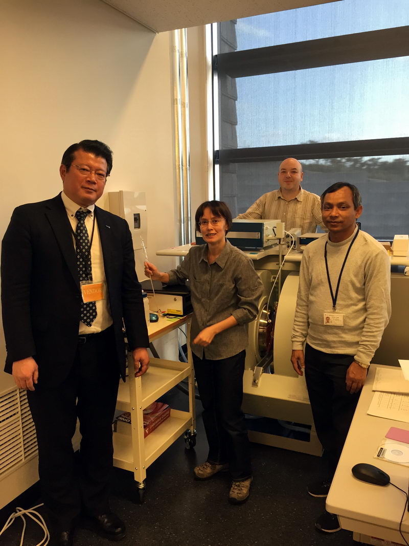
Here is the picture from the last day of ESR installation:
Left to right: Mizuta-san (JEOL), Julia, Eugene (at the back), Roy-san.
Kanai-san from JEOL is not in the picture, since he left one day earlier.
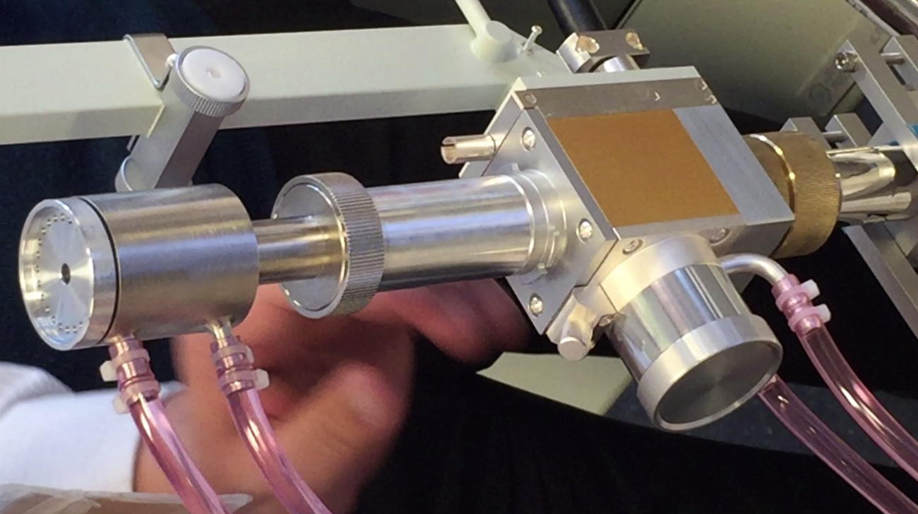
I am holding an electrolysis ESR cell and looking happy because I know I’m going to spend next several days doing something with it that has absolutely no practical meaning (but I will talk about it briefly at the end of this post and leave the rest for the next one). Read more...
So on the first day, we did several tests at room temperature, including:
- Overmodulation check
- Power saturation check
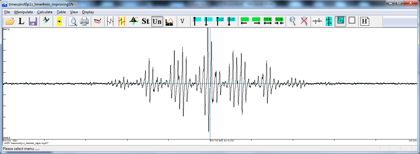
- Improving signal-to-noise ratio by changing time constant (and sweep time)
As a result, here is a final well-resolved spectrum of perylene radical:
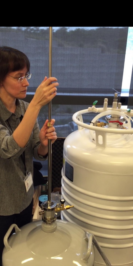
Then, Kanai-san and Mizuta-san from JEOL assembled the cryostat:
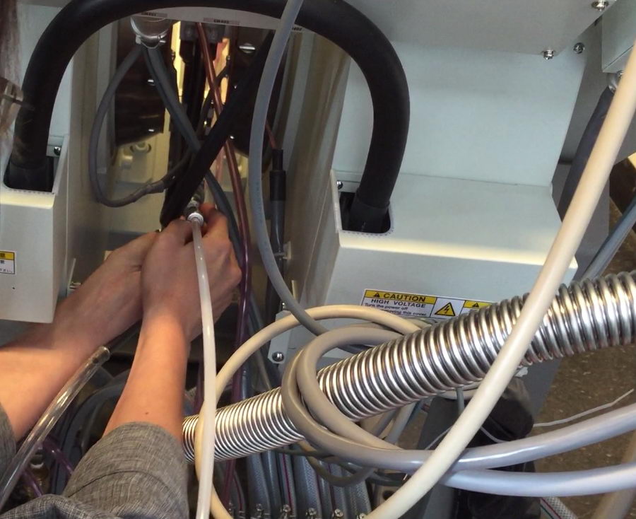
We tested the low temperature VT system:
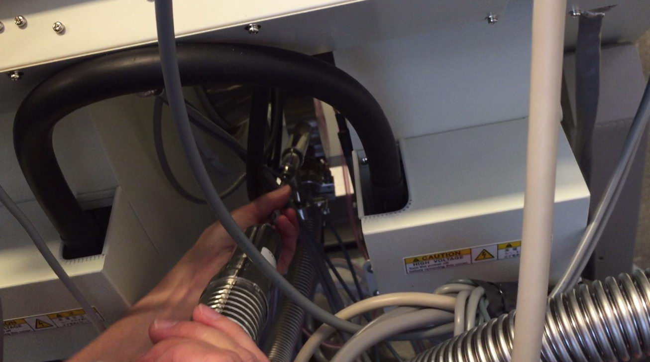
Not without occasional disasters, such as water splashing all around power supply and a vacuum pump:

We also tested high temperature VT (although it’s a bit unlikely we’ll use this function very often):
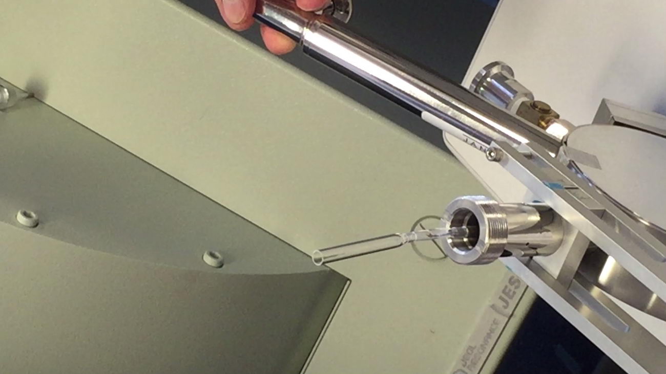
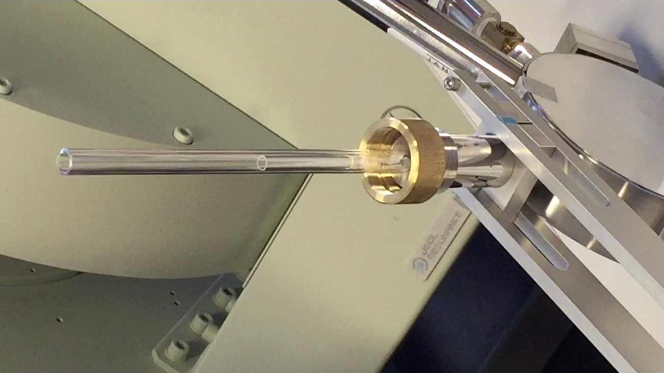
Eventually, we started testing the electrolysis cell for one-electron oxidation of one of the complexes that should give a paramagnetic species.
The electrolysis cell is a quartz tube with gold working and auxiliary and silver pseudo-reference electrodes inserted inside.
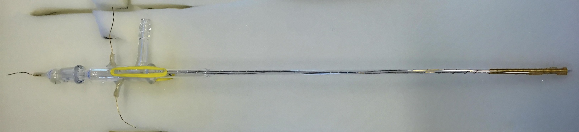
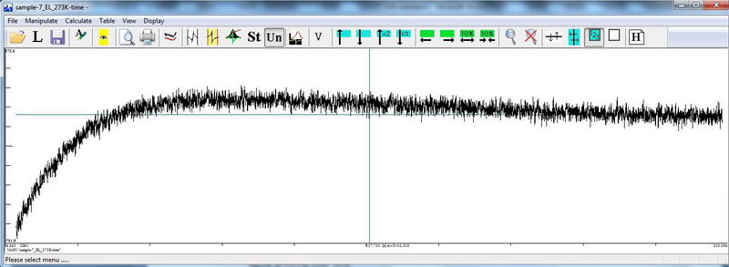
It generally worked in a sense that we got a signal that grows over time during electrolysis. However, the signal starts decaying too soon, even though the product should be stable and the solution is cooled down to 273K. This could be due to many reasons: overoxidation if the potential was not set correctly; diffusion of by-products from the auxiliary chamber, etc.
That’s why we attempted to take a CV in this electrolysis cell, to check where the potential should be vs. a pseudo reference electrode (silver wire).
At slow scan rate, the CV looked almost reasonable:
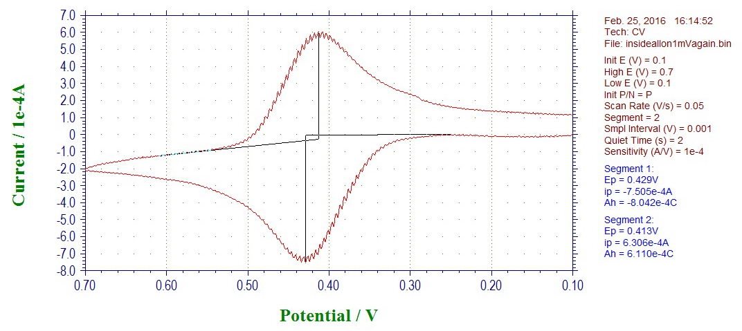
There is a noise at 10 Hz, which initially looked intriguing (but later was deciphered as 60 Hz from AC at slow sampling rate of 50 points per second, every 1 mV at 50 mV/s scan rate). While trying to figure out the source of this noise, a CV of a model compound was recorded at a higher scan rate, 500 mV/s, which gave a slightly more complicated picture:
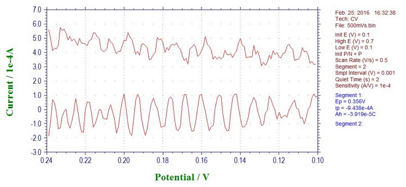
This looks a bit more complicated than the simple noise from 60 Hz AC and it took a little while to figure out what else is in there, but I’ll leave it for the next post.