

DIY Oxygen Concentrator
Preamble
Author: Mahesh M. Bandi, Nonlinear and Non-equilibrium Physics Unit, OIST Graduate University.
This is open-access information made freely available for anyone to use. The information provided here works for parameters that apply to our specific implementation. We provide no guarantee nor accept responsibility for any implementation or use derived from information provided here. The user is advised to proceed at their own discretion.
I did not have the luxury of a lab for this implementation. Everything was constructed from locally sourced parts and the system was built in my parents' apartment building parking lot in India.
Table of Contents
1. Introduction
This webpage was created in response to the acute shortage of medical grade oxygen being faced in several countries currently due to the covid-19 pandemic, especially India where the second wave of infections are hitting unimaginable new highs.
The air we breathe contains approximately 21% oxygen, 78.1% nitrogen, and trace amounts of other rare gases. Medical grade oxygen consists of 95% or more oxygen. From this video tutorial on preparing one's own makeshift intensive care unit (ICU) for a patient with serious COVID-19 (the video is in Hindi, but has English subtitles), I realized the essential part of such an isolation unit is primarily the oxygen supply.
I am neither medically trained nor am I qualified to make any intelligent remarks on the aforementioned video. But given the shortage of medical grade oxygen, I reverted back to my past, to when I needed a decent quantity of pure oxygen but lacked the funds for it. However we had an air compressor in the lab that allowed us to slap together a home-built oxygen concentrator. The design presented below is a reconstruction of that past effort.
1.1 Selecting the suitable method.
The above video mentions a COVID-19 infected patient may need between 5 - 15 liters of oxygen per minute. It's not easy to achieve oxygen production in such quantities through electrolysis in a domestic setting. Chemical oxidation reactions on the other hand are unstable (explosive) and just not advisable in a domestic setting.
Oxygen concentrators are an attractive solution since they use atmospheric air freely available in unlimited quantities in our surroundings as their input and they are relatively safe. They do not involve cryogenic liquefaction of oxygen as is done with cylinders, so this cuts out huge engineering hassle and makes their design quite simple and tractable.
The method involves passing air through a bed of grains called artificial zeolites. The nitrogen is adsorbed (with a "d", not a "b", meaning it sticks) onto zeolite molecules and most (but not all) oxygen is allowed to pass through.
Assuming all nitrogen in the air passing through the zeolite is adsorbed, for every 100 liters of air pumped through the bed, we remove 78.1 liters of nitrogen and are left with almost (not all) 21 liters of oxygen and less than a liter of other rare gases. Terefore, the 21.9 liters of gas exiting the zeolite bed contains (21/21.9)x100 = ~ 95.6% of oxygen, which meets medical grade specifications. The crucial point is the assumption that all of the nitrogen in the air is being removed by the zeolite bed, and most of the effort goes into ensuring that.
2. System Design
2.1 Oxygen Concentrator - Process Flow
The design below is scalable from portable units for individual use that are commercially sold to larger installations that some hospitals use to produce their own medical grade oxygen. What changes from the portable to institution-scale systems is the compressor size and the quantity of zeolite needed for concentrated oxygen production. Otherwise, the process, which is shown in the flowchart below (Figure 1) is identical between the two scales.
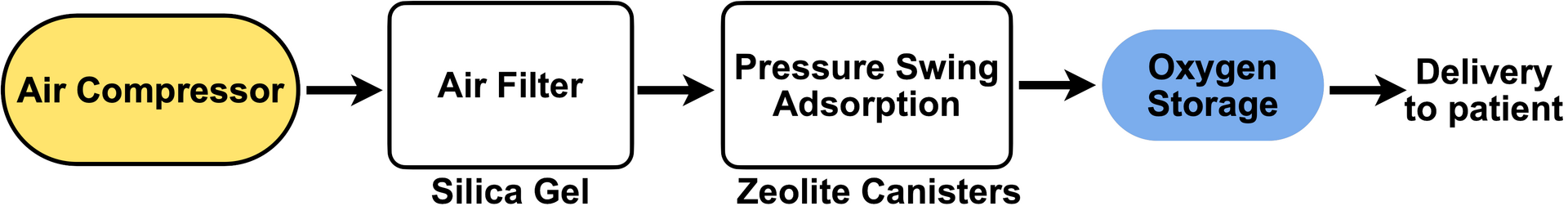
The basic process requires an air compressor that pumps air at a pressure above the standard atmospheric pressure through an air filter. The air then passes through a chamber containing the zeolite crystals that remove nitrogen, and out comes medical grade oxygen that is stored in a tank before being supplied to patients. Now we get into the specifics of each step in the above process.
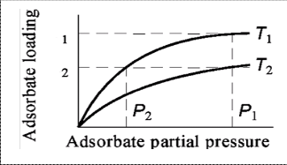
We start by shooting down our earlier assumption -- that all nitrogen in the pumped air is removed by the zeolite crystals: it is not. I will not get into an involved discussion of the thermodynamics of sorption kinetics and adsorption equilibria, the interested reader is referred to this study. Simply put, the amount of nitrogen removed by zeolite depends on both temperature and pressure of air (see Figure 2 for a representative pressure curve). The fraction of nitrogen removed by zeolite from incoming air increases with decreasing temperature (T1 < T2 in Figure 2 above) as well with increasing pressure (P1 > P2 in Figure 2 above).
2.2. Compressed Air and Filtration
Although temperature is more readily manipulated in domestic settings, higher pressure does better for nitrogen adsorption in the present context, and pressurized air can be more easily achieved than we realize. Every gas station (petrol pump, if you're in India), welding shop, and auto shop has an air compressor in India. Portable car tire inflators are basically the same, just in a compact form.
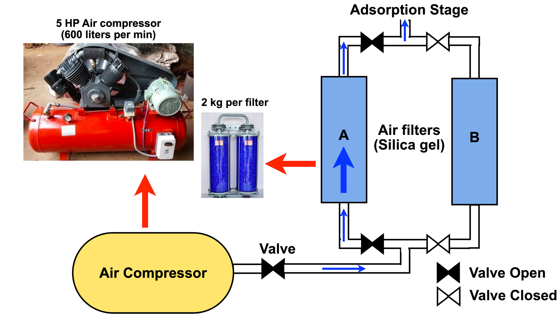
Whether you pick an industrial size air compressor as I did (see inset in Figure 3 above), or a portable car tire inflator, make sure you select one capable of going up to to 6-8 bars of pressure (if you're more comfortable with PSI, pounds per square inch, 1Bar = 14.5 psi). The compressor I used is an Ingerrsol Rand 5 HP air compressor (purchased second-hand for INR 14000, approx. JPY 20000) capable of processing 600 liters per minute of air. If purchasing a new one, try to pick one that is oil free, but it's not important.
As shown in Figure 3 above, we connect the output from the air compressor to a HEPA filter or an air filter with silica gel. Air contains water vapor, plus if you use an old compressor as I did, the pressurized air from the compressor also contains tiny oil droplets. Zeolite crystals adsorb both vapor molecules and oil, and any zeolite surface occupied by vapor or oil is then unavailable for nitrogen adsorption, which means that the efficiency goes down. In fact, zeolite adsorbs vapor molecules far more readily (even at atmospheric pressure) than nitrogen, the reason being that water is polar and more readily attracted to zeolite whereas nitrogen interacts via a quadrupole moment. For this reason, its essential to pass the pressurized air exiting the compressor through a HEPA filter or a silica gel dessicant that can absorb vapor and oil.
In the design above (see Figure 3), I used two silica gel dessicant air filters in parallel. I use filter A initially, and once it saturates with vapor and/or oil, I shut off the valve and re-direct incoming pressurized air to filter B and hot-swap a new filter in place of A to ensure continuous operation. About 2 kg of silica gel per filter can last a few hours, depending on the liters per minute of air processed by the system. The swapped out air filter is then opened and the moisture in the silica gel can be removed by heating it at 110oC. You can use a convection oven or gently heat the silica gel on a stove and it's ready for reuse. If you have a convection oven, its advisable to pre-heat the oven and bake the silica gel for 20 minutes at 150oC. If heating on a stove, use a baking/oven thermometer to take it up to 110oC and keep gently turning over the silica gel particles for 1 hour.
Word of caution: In a cheap early version, I tried to bubble the compressed air through a bottle of glycerine since it is both hygroscopic and oleophilic. But the bubbling causes huge pressure fluctuations at the next stage and the process was a disaster. HEPA or Silica gel air filters cut out these fluctuations, and in fact, owing to Darcy's law, they even smooth out the fluctuations, although this also causes a pressure drop at the output end of the filter.
Before we proceed to the next and most crucial stage of the concentrated oxygen generation process, I will take a small digression to explain a bit about zeolites -- the material used to adsorb nitrogen. Zeolites are a class of microporous aluminosilicate materials commonly used as adsorbents and catalysts because they act as molecular sieves. This property arises from removal of their "water of crystallization" which leave behind a porous structure or cage at the molecular scale. These pores or cages can accommodate a wide variety of cations (positive ions) including sodium, potassium, calcium, magnesium, which are loosely held. These cations can be readily exchanged with other molecules by external application of pressure, or thermal or electrical forces.
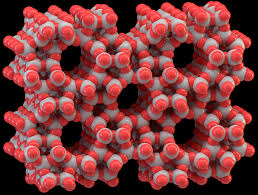
Zeolites are a family of such molecular sieves comprised of various compounds, some of which occur naturally, but many are synthezied artificially for industrial applications. For reasons unknown to me, it turns out India is a major producer of zeolites. They are used as catalysts in fractionation of hydrocarbons, as dessicants for water removal, and as in our present case, for separation of gases.
In particular, for our purpose, two types of artificial zeolites, known as Zeolite 5A and 13X are suitable for nitrogen adsorption from air at low temperatures and/or high pressures. Now, all gases that make up air are non-polar; we know from elementary chemistry that oxygen and nitrogen molecules are electrically neutral and the existence of the molecule itself is due to electronic stability. Then why does nitrogen adsorb to Zeolite 5A or 13X whereas oxygen does not?
The reason is owed to a higher order interaction between zeolite and air. The positive charge on the zeolite molecule induces a quadrupolar moment in both nitrogen and oxygen, but it is three times stronger in nitrogen than it is in oxygen. For this reason, far more nitrogen gets attracted to the zeolite crystal surface, whereas oxygen passes through the pore or cage. However, we know quadrupolar interactions are much weaker than dipolar interactions, and for this reason desorption (i.e. removal) of nitrogen from the zeolite matrix is also easily achieved. Much of the process described below in the subsection 2.3 on Pressure Swing Adsorption concerns the initial adsorption, followed by subsequent desorption of nitrogen in a cyclic fashion to achieve continuous concentrated oxygen generation. Between Zeolite 5A and 13X, Zeolite 13X exhibits much higher selectivity towards nitrogen.
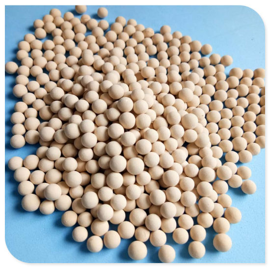
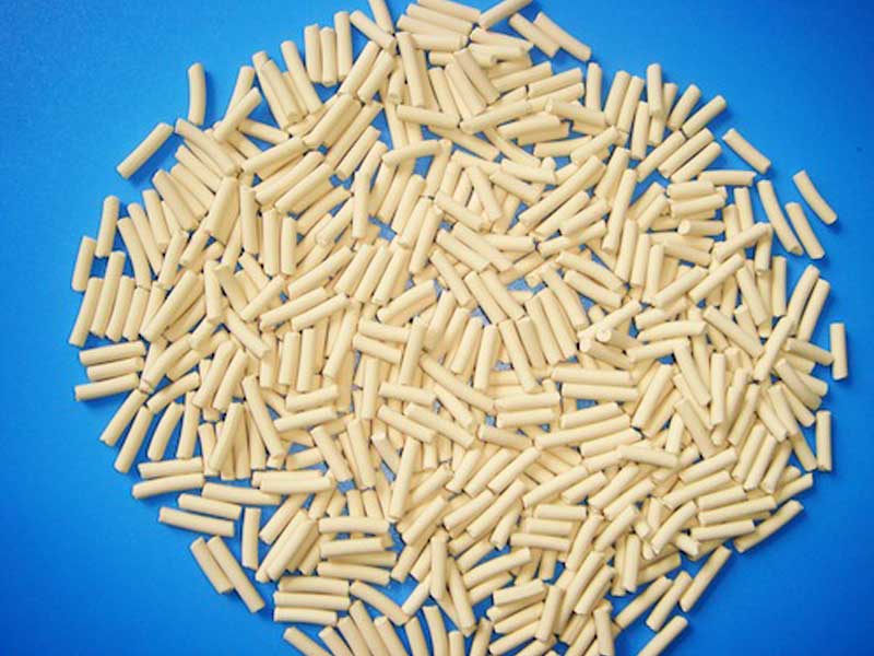
Commercially, Zeolite 5A and 13X are manufactured as spheres or cylinders at macroscopic scales, as shown in Figure 5 and 6 below.
2.3 Pressure Swing Adsorption
Once the pressurized air passes through the HEPA or dessicant filter, it enters the crucial stage of nitrogen removal from air. This stage is commonly known as Pressure Swing Adsorption (PSA) because it involves a series of four steps repeated in a cycle for continuous generation of pure medical grade oxygen. The schematic is shown together with step 1 of this 4-step procedure. Although the schematic looks rather complicated, it is quite simple and mostly involves plumbing.
First, a brief description of the structure. I took two aluminum cylinders and filled the bottom with a bed of glass marbles and poured Zeolite 13X into the cylinders. After jiggling the cylinders to compact the zeolite beads, a second bed of glass marbles formed the top layer. These two cylinders form the zeolite canisters Z1 and Z2 in the schematic below (see Figure 7).
Word of caution: An early version of zeolite canister made with PVC pipe was a disaster. I used a pipe that wasn't thick enough to handle the pressure. Secondly, PVC pipes have to be glued to seal them airtight and if anything goes wrong they have to totally discarded. Instead, metal canisters (see Figure 7 inset and Figure 10 inset below) can be sealed with gaskets or O-rings and can be held together with screws. This makes it easier to replace the zeolite if necessary. This is particularly true if water vapor invades the zeolite canisters. As it takes much higher pressures and/or temperatures to remove the water, instead it's easier to simply replace it with a fresh batch of zeolite beads.
A second problem comes from the tubing. If you use cheap, collapsible PVC tubes, they easily kink and cause pressure blow outs. Use either thick PVC tubing used in vacuum applications as I did for the portable version or copper tubing as I did for the larger version. It is more stable.
The canisters were sealed with gaskets. The filtered compressed air enters the bottom of a pipe that bifurcates in two.
In step 1, we open valve V2 and close valve V4 to operate canister Z1. Valve V1 should be closed, else the compressed air escapes directly back into the room. Keeping V2 open and V1 shut allows the filtered air to pass through the zeolite bed at 6-8 bars of pressure and purified oxygen is released from the top end. By keeping valve V5 closed and V6 open, the purified medical grade oxygen can exit to a storage cylinder.
The inset in Figure 7 shows a portable working version of the two aluminum zeolite canisters and the associated plumbing. This was run with a portable car tire inflator and produced 9 liters of purified medical grade oxygen per minute.
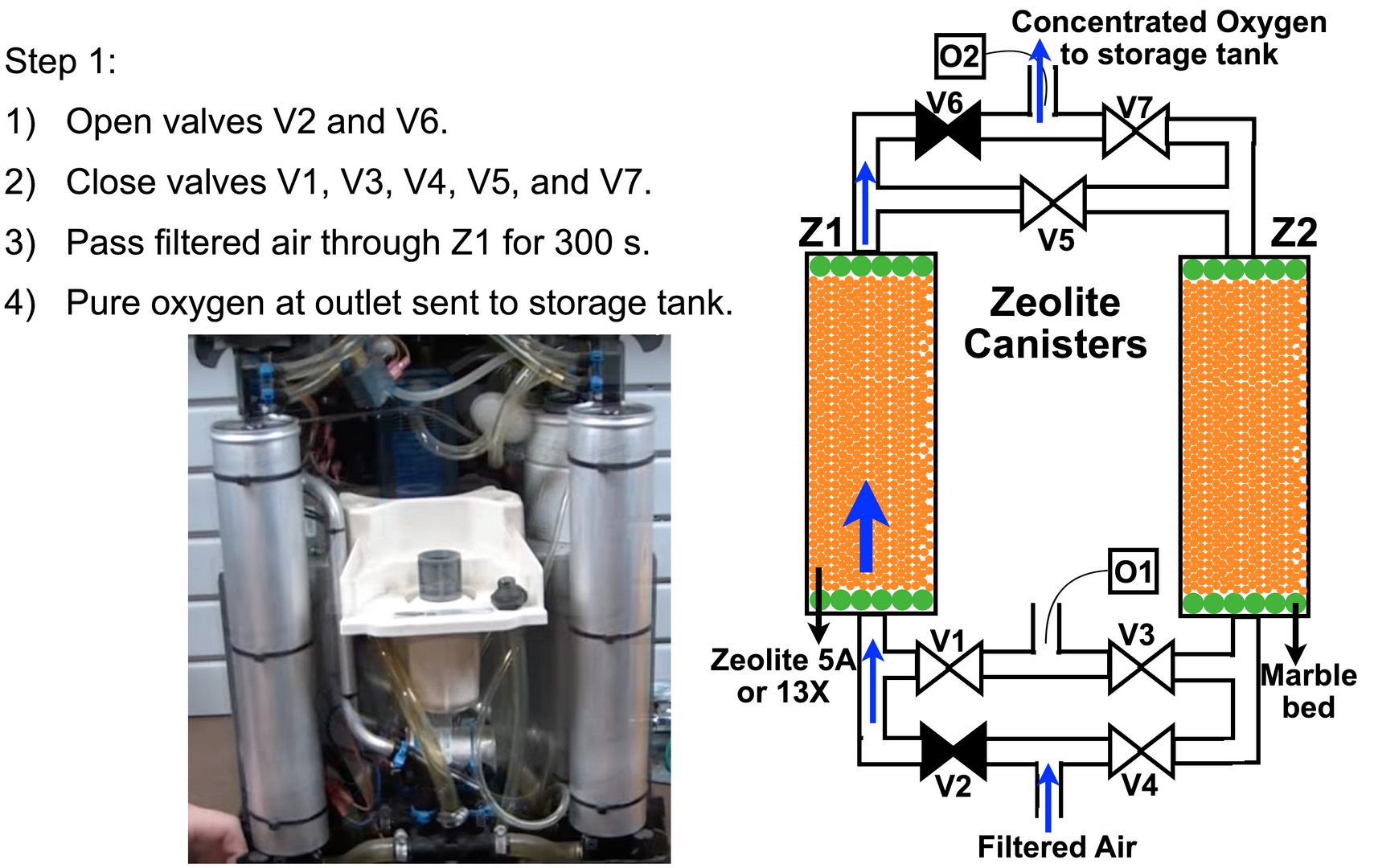
The zeolite is soon saturated with nitrogen, and the process must stop before this happens. How long one can produce oxygen with a single canister depends on the pressure and quantity of zeolite used. The portable version had canisters of 5 cm in diameter and 20 cm in height. But the larger version shown in inset of figure 10 using the larger 5HP air compressor used canisters of 25 cm in diameter and 1 m in height. These large canisters could run 450 - 470 seconds before the zeolite was saturated with nitrogen. To be on the safer side, we stopped this step 1 after 300 seconds. Later, I will explain how the calibrations were performed to work out the saturation time, so you can perform them on your own system.
The step 1 process for pressure swing adsorption is described in Figure 7 above.
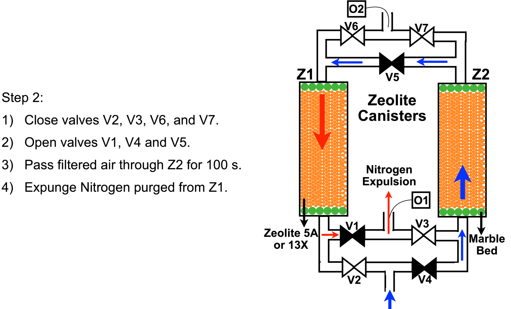
After step 1 is completes, in step 2 we close valve V2 and open valves V4 and V5, but keep V3 and V7 closed and pass the compressed air through canister Z2. The purified oxygen coming out of Z2 passes through V5 into canister V1 and purges its zeolite bed of the adsorbed nitrogen. Opening valve V1 then releases this nitrogen into open air. See schematic and the outlined steps in Figure 8 above.
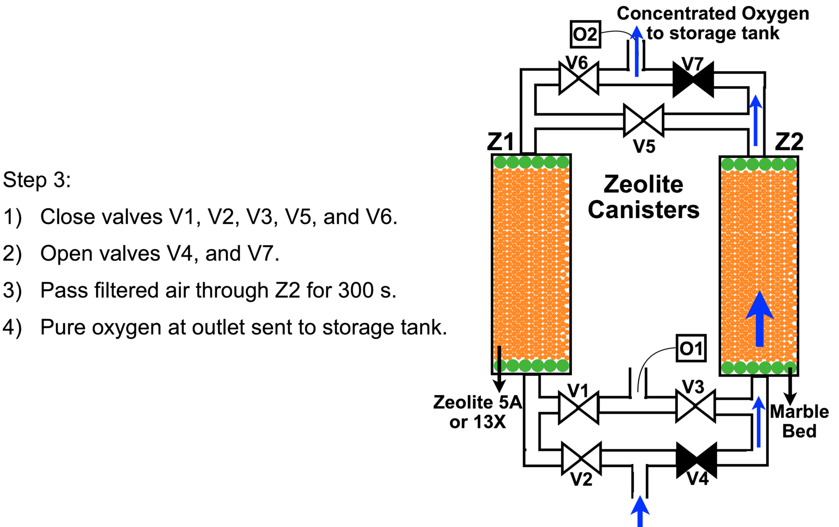
After purging nitrogen from Z1 for 100 seconds in step 2, in step 3 we shut off valve V5 and open valve V7 to let pure oxygen into the storage cylinder for 300 seconds. By now canister Z2 has run for a total of 400 seconds and is saturated with adsorbed nitrogen.
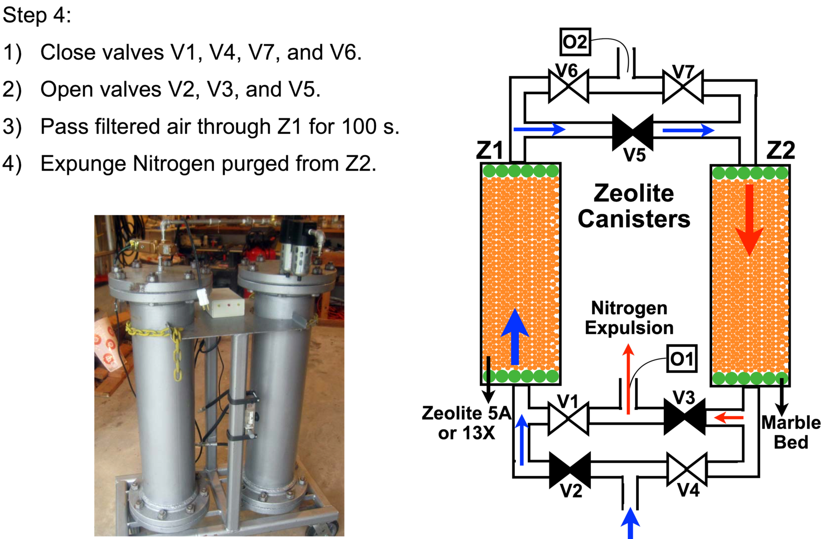
Now in step 4, we close valve V4 and re-open valve V2. But we do not open valve V6. Instead we open valves V5 and V3 so the compressed air enters canister Z1 and the purified oxygen passes through V5 to enter canister Z2 to desorb nitrogen from its zeolite bed. This process runs for 100 seconds before valve V5 is shut off.
We then repeat steps 1 - 4 and cycle through in order to get continuous oxygen output.
This four step cyclic process is standard for both portable and industrial scale oxygen concentrators and is known as Pressure Swing Adsorption, because the pressure is applied in step 1 to adsorb nitrogen and produce oxygen, then it is swung in step 2 to purge the saturated nitrogen from canister Z1 using the pure oxygen produced by Z2. In step 3, pure oxygen is collected again from Z2 before it gets saturated at the 400 second mark. Finally in step 4, the re-generated zeolite bed in canister Z1 is used to purge saturated nitrogen from canister Z2 for 100 seconds.
Doing so is beneficial because in older processes, the nitrogen purge was performed by shutting of air supply and applying a vacuum to suck out nitrogen, but this would involve a second external line which would introduce short quantities of water vapor between line switches and would eventually degrade the zeolite canisters beyond use.
The pressure swing adsorption process allows near continuous oxygen output, except for the 100 second durations in steps 2 and 4 when it is used to purge nitrogen from zeolite canisters. For this reason, the last stage involves a storage tank. The tank provides continuous supply of medical grade oxygen to patients in need so that they do not notice the oxygen output cut off for 100 second duration in steps 2 and 4. Furthermore, the storage tank also acts like a capacitor does in electrical circuits to smooth fluctuations. Just as a capacitor stores charge, the tank stores oxygen, and if there are any pressure fluctuations upstream, they are smoothed out by the stored oxygen.
In my implementation, I used a 20 liter cylinder for oxygen storage in the portable version and a 250 liter gas tank in the larger version. Whereas the portable version was useful for individual use, the large version provided a central generation line that could continually supply up to 10 patients self-isolating in a house.
2.4 Oxygen Sensors and Calibrations
The 100 and 300-second durations applied in the above steps were determined from calibrations I performed on these home-built canisters. In order to do so, I had to embed oxygen sensors to measure both the purity and the duration for which each canister would output purified oxygen before its zeolite bed was saturated with nitrogen.
Ideally, I would have liked to use both oxygen and nitrogen sensors, but I was unable to source nitrogen sensors locally. So as I explain below, I used oxygen sensors as a proxy.
The schematic shown in Figures 7 - 10, has two sensors O1 and O2 at the nitrogen and oxygen outlets. The sensor O2 operates as a normal oxygen sensor, but O1 sensor placed near the nitrogen expulsion outlet detects for end of nitrogen purge when pure oxygen starts being expelled. This sets the duration for nitrogen purge.
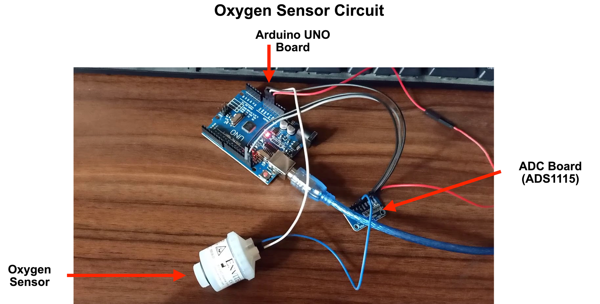
I used two medical grade OOM202 oxygen sensors from Envitec. This point is important -- since air contains approximately 21% oxygen, most cheap oxygen sensors can only detect oxygen in the range 0 - 26%. Medical grade oxygen sensors used in ventilators can detect oxygen over the entire range of 0 - 100% oxygen level.
The OOM202 is an active sensor that does not require an external power source and provides output in the range of 13 - 16 mV. Since this voltage level is low for Arduino detection, I used an analog-to-digital convertor (ADC) with a gain before interfacing it with an Arduino UNO target board. The ADC I used is ADS1115 that mates easily with the Arduino.
The OOM202 sensor had three pins, of which the ground pin (white wire in Figure 11 above) and analog output (blue wire in Figure 11) are used. The analog output is connected to A0 terminal of the ADS (ADS1115) whereas the white cable is connected to GND port of the Arduino UNO target board. The ADS1115 has two outputs, the SCL and SDA pins which connect to the corresponding SCL and SDA pins on the Arduino UNO target. The ADS1115 takes a 5 V power input and a ground connection, both of which are drawn from the UNO target. This completes the circuit.
The sensor was inserted in the outlet pipe wall. Its 13 -16 mV output is converted by the ADC to a digital output in the range 70 - 350 (70 being 0% oxygen and 350 being 100% oxygen reading). In total each sensor (Rs. 4000), UNO board (Rs. 500) and ADS 1115 (Rs. 500) system cost Rs. 5000 (approx. 7200 yen).
The arduino target was run from a laptop using serial interface. The program I used is pasted below for your reference.
Adafruit_ADS1115 ads(0x48);

Void setup(void)
{
Serial.begin(9600);
Serial.println(“Single reading from AIN0...3. ADC Range:+/- 6.144V (1 bit = 3mV/ADS1115, 0.1875mV/ADS1115)”);

ads.begin();
}

void loop(void)
{
int16_t adc0, adc1, adc2, adc3;

adc0 = ads.readADC_SingleEnded(0);
adc1 = ads.readADC_SingleEnded(1);
adc2 = ads.readADC_SingleEnded(2);
adc3 = ads.readADC_SingleEnded(3);
Serial.print(“AIN0: “);
Serial.print(adc0);
Serial.println(“ “);

delay(1000);
}
The above code was taken from here and modified slightly because I do not read channels A1 - A3, I use only channel A0 to read the oxygen sensor output. Basically the first function called setup initializes the ADS1115 ADC board and the second function named loop reads the ADC output with a delay of 1000 cycles, which translates to 1 second. So I was able to get the oxygen sensor read out in 1 second time-steps to calibrate the oxygen purity and time duration of each step in the pressure swing adsorption cycle.
The sensor voltage range and associated ADC output may vary from one sensor to the other, but otherwise the hook up and implementation is very simple.
I will upload the calibration graphs in a day or two once I can find time to replot them. Please stay tuned.
3. Concluding Remarks
The above system is simple; you may at most need help from a welder and plumber, but the rest is quite straightforward. The portable design shown in Figure 7 provided an output of around 9 liters per minute and the larger one provided a little over 100 liters per minute. Both canisters were overdesigned for safety after the blow out of my first PVC canister. Also, I used Zeolite 5A for the portable canister, and it gave me 90.7% pure oxygen -- almost but not medical grade (95% purity). So I switched to Zeolite 13X for the larger implementation, and this got me to 92.5% purity oxygen.
Also, my design requires a person to manually turn on and off the valves every few minutes. This is obviously cumbersome. I wanted to use solenoid valves and design an automated control system that would provide continuous running at the turn of a switch, but I don't know where to source solenoid valves locally right now. If I get to it, I will upload the control system design in a few days.
Finally, please make sure you place the zeolite canisters in a shaded area away from the sun, lest the heat change the purity of the oxygen since temperature also impacts operational efficiency. I placed the compressor on the ground floor and ran the line upstairs and placed the zeolite canisters and storage tank on the balcony (we don't want nitrogen flooding the indoor area). The line was then run from the balcony to patient's bed indoors.
May 4, 2021 Update: Few details I've been repeatedly asked.
1) Please realize, this isn't my science or design. The science was worked out in the 19th century and the design is industry standard since 20 years. I merely implmented it using parts readily available at a local plumber's junk and help from a welder in the street corner.
2) This isn't a certified system nor will it pass certification. My choice was between my folks having to breathe air with 21% oxygen or none at all. I didn't care if its medical grade, any purity level I could reach within the constraints I faced and tools I had access to was worth trying. For the same reason, there's nothing special about use of copper tubing and such. I made do with whatever I could find on short notice.
3) The system loses efficiency with time throughout the day and resets overnight. This is due to diurnal temperature rise in the Indian summer which reduces zeolite efficiency.
4) I never bothered with the cost, I know nothing about it. And I've been working in sub-optimal conditions, more like a theoretical experimentalist, not having a lab has been extremely limiting.
5) The efficiency rise is tough beyond a point because the pressure isotherm starts plateuing at higher pressures. See figure 2.
6) I found the efficiency is also sensitive to the way zeolite is packed. I don't understand why.
7) The storage tank I used was a steel drum used to store grain in South India that I welded airtight. Its not rated for high pressure gas storage. So I added a pressure regulator from a bicycle pump and stored oxygen in it only up to 30 psi (roughly 2 bar) pressure.
Finally, I've received several helpful pointers and pointed questions from colleagues who include: Prof. Arnab Bhattacharya (TIFR, Mumbai), Prof. M. Krishnamurthy (TIFR, Hyderabad), Prof. Abhishek Dhar (ICTS, Bangalore), Prof. Srikanth Sastry (JNCASR, Bangalore), Prof. Santhosh Ansumali (JNCASR, Banagalore), Prof. Meher Prakash (JNCASR, Bangalore), Prof. Diwakar Venkatesan (JNCASR, Bangalore), Prof. Prapanch Nair (IIT, Delhi), Prof. Narsing Kumar Jha (IIT, Delhi). The following points were copy-pasted ad verbatim from Prof. Ansumali's email to me:
Hope this is useful.
Terms and conditions

This work is licensed under a Creative Commons Attribution-NonCommercial-ShareAlike 4.0 International License.
The work is © Okinawa Institute of Science and Technology 2020. It is being shared via the OIST group website under a Creative Commons Attribution-Non Commercial 4.0 International Public License.
Please note the terms and conditions set out in the license, and in particular note the cautionary note and disclaimer in the Preamble.