

"Cut the red one!!!"
There is sometimes a question when people start doing CV measurements about cable connections: which cable to connect to which electrode? So we have a green one, a red one, and a white one. To give a final reference point for CV experiments and solve this question once and for all, let’s have a look again at the correct way of connecting cables to the electrodes in the three-electrode cell for CV experiments. And I’ll also show what happens if you do it in the wrong way.
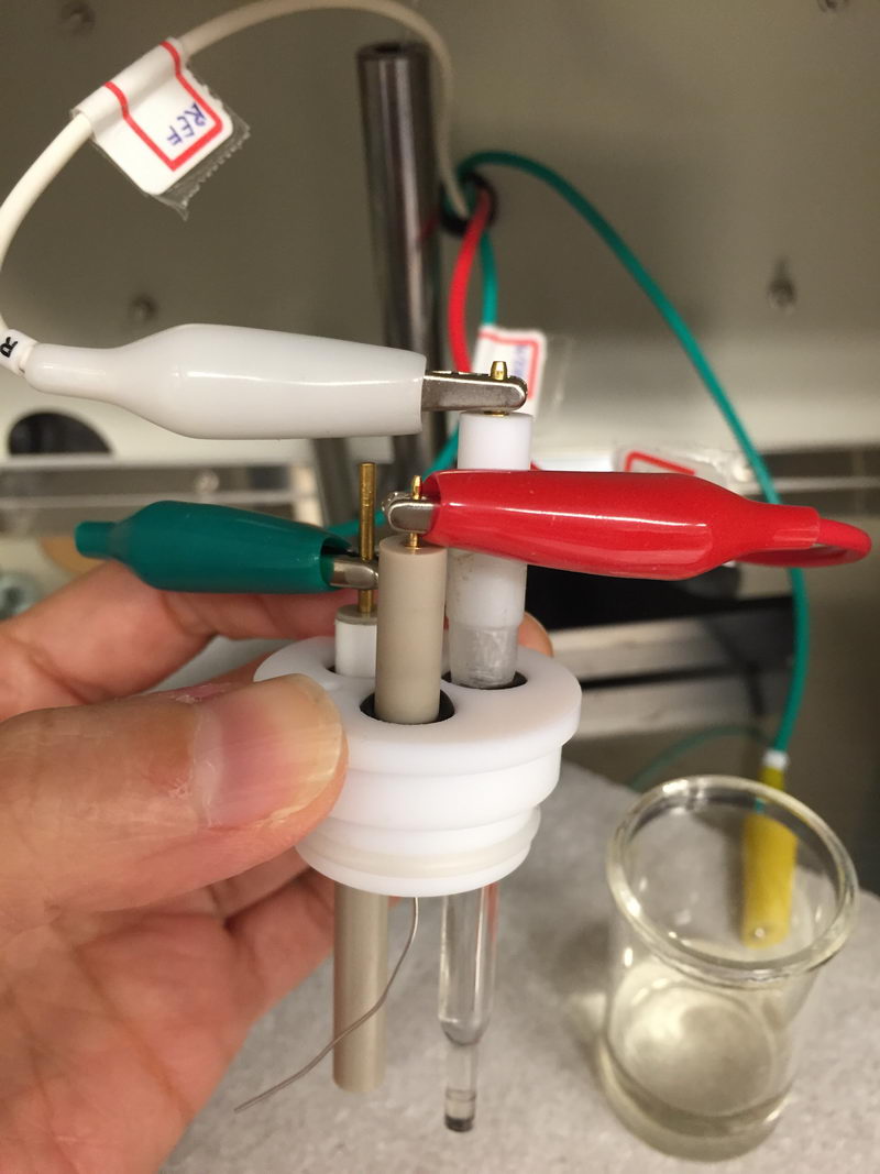
What we have in the CV cell is (a) a reference electrode; (b) working electrode (Pt or glassy carbon disk electrode), and (c) auxiliary electrode, usually Pt wire. All our cables are labeled as follows:
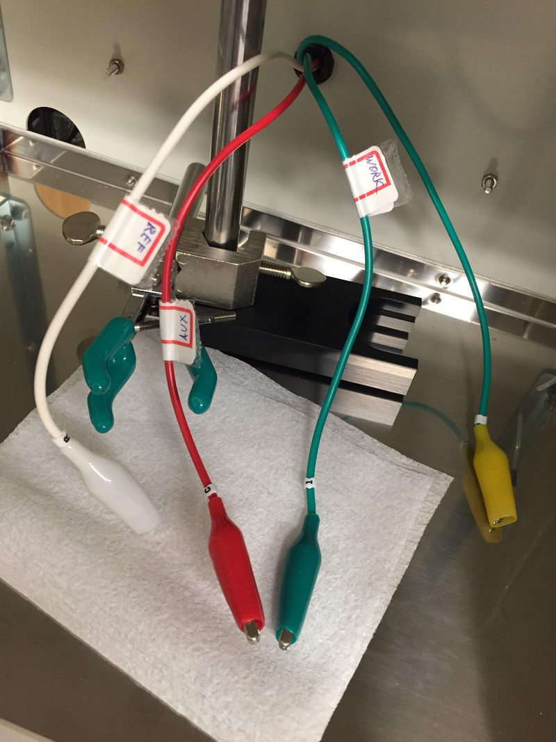
- White cable – “R” or “REF” label – connect to reference electrode. This is usually Ag/AgCl/3M NaCl for aqueous solutions and Ag/AgNO3 (10 mM)/0.1M TBAP/MeCN for non-aqueous solutions, or sometimes a silver wire pseudo-reference. Luckily, our non-aqueous electrode has a white cap, so it looks natural to connect it to white cable….
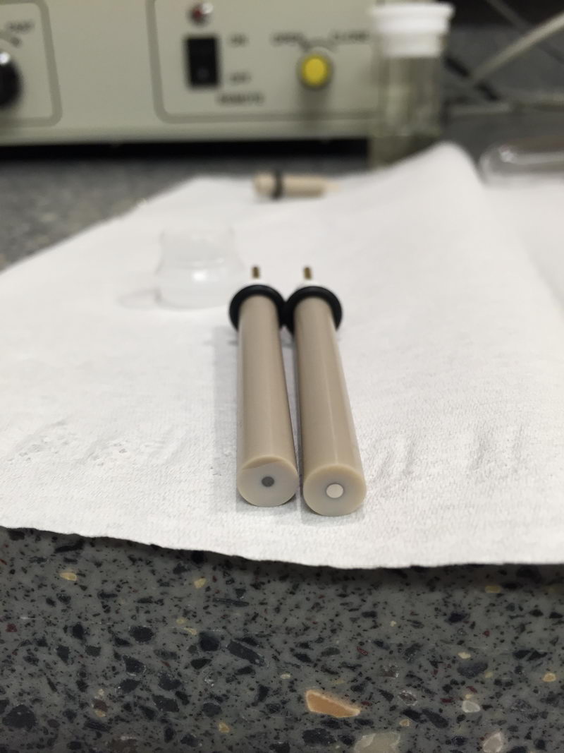
- Green cable – “1” and “WORK” labels: connect to working electrode. This is usually glassy carbon or platinum disk electrode (1.0 or 1.6 mm diameter) for CV experiments. If you look at the picture below, the black disk on the left is glassy carbon (GC) and the disk electrode on the right with metallic color surface is Pt electrode. For electrolysis, working electrode that we use is usually Pt mesh or porous carbon
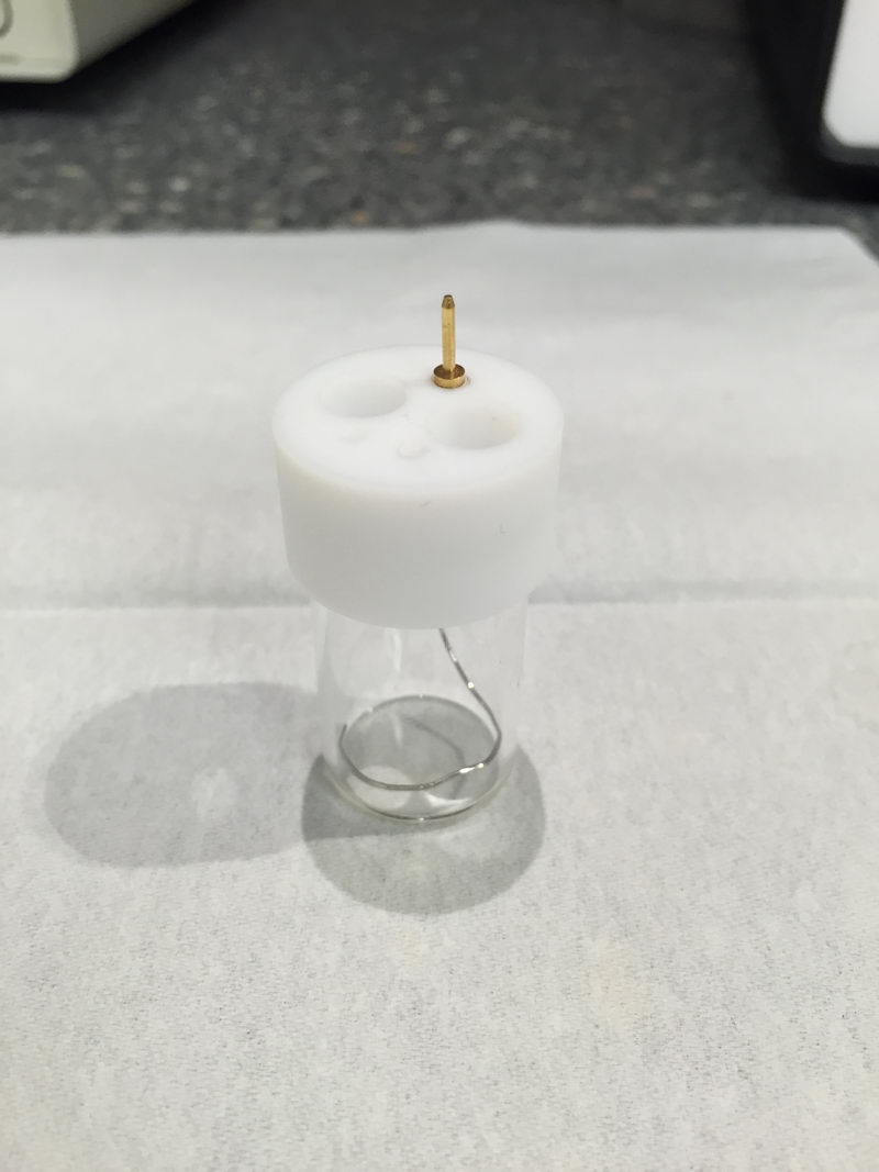
- Red cable – labeled as “C” (meaning counter-electrode) and “AUX” (stands for “auxiliary electrode", which is the same) – connect to auxiliary, usually Pt wire (see below how it looks for small volume cell). For electrolysis, it would usually be Pt mesh or Pt coil in a separated auxiliary chamber.
We have a fourth cable (yellow) that we rarely use, labeled as “2”: it is a second one for working in case of high currents (I think over 10 mA would qualify for this). Normally, we don’t need it for CV.
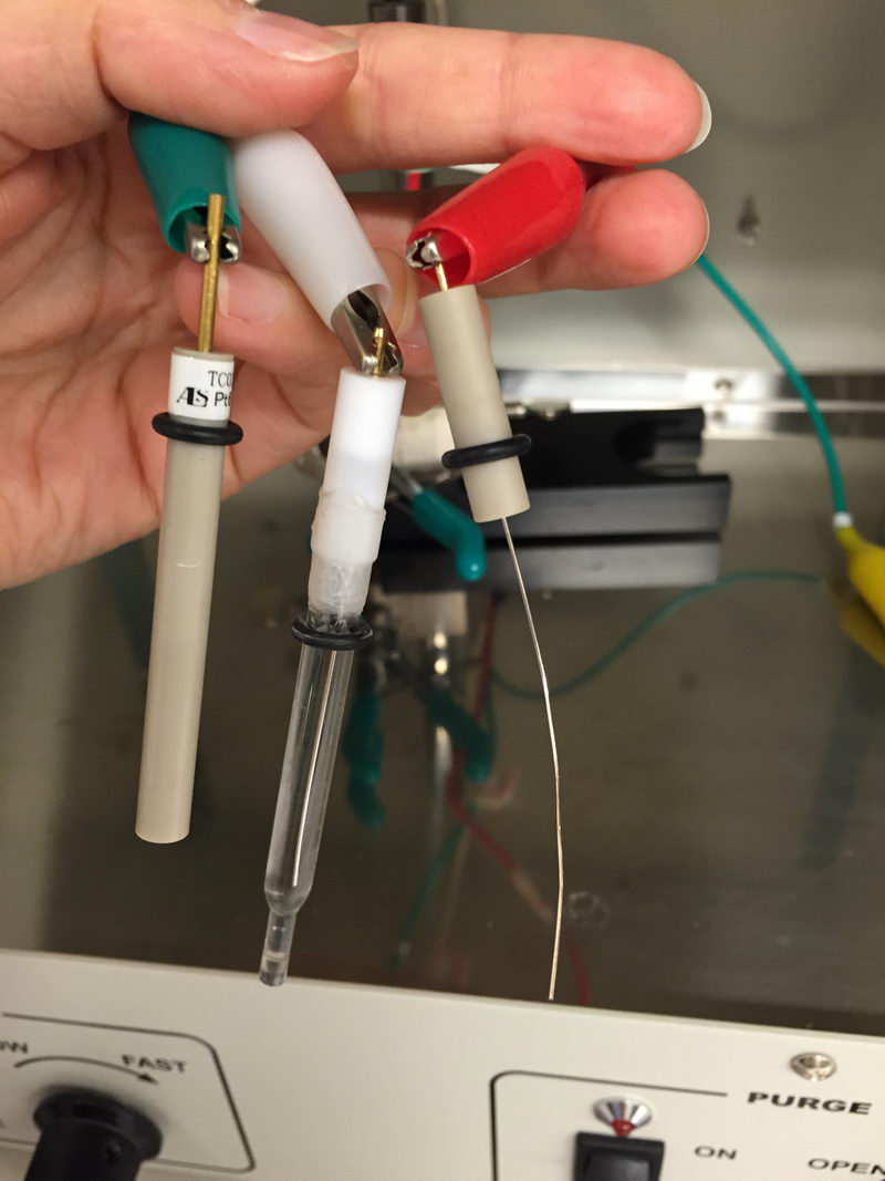
The CV cell will be connected like this:
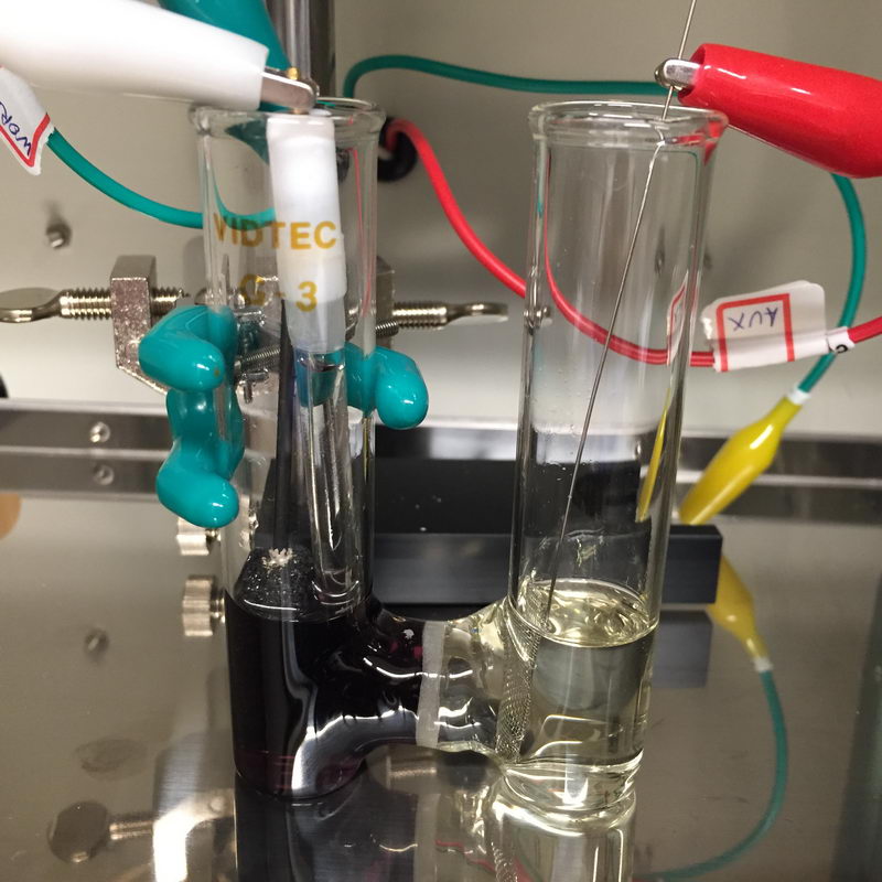
And electrolysis cell will look something like this (hard to see the green one, but it’s on the left side, connected to porous carbon on graphite rod):
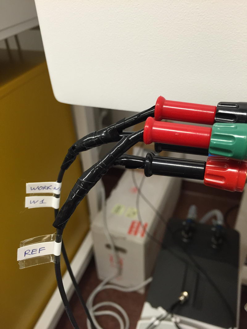
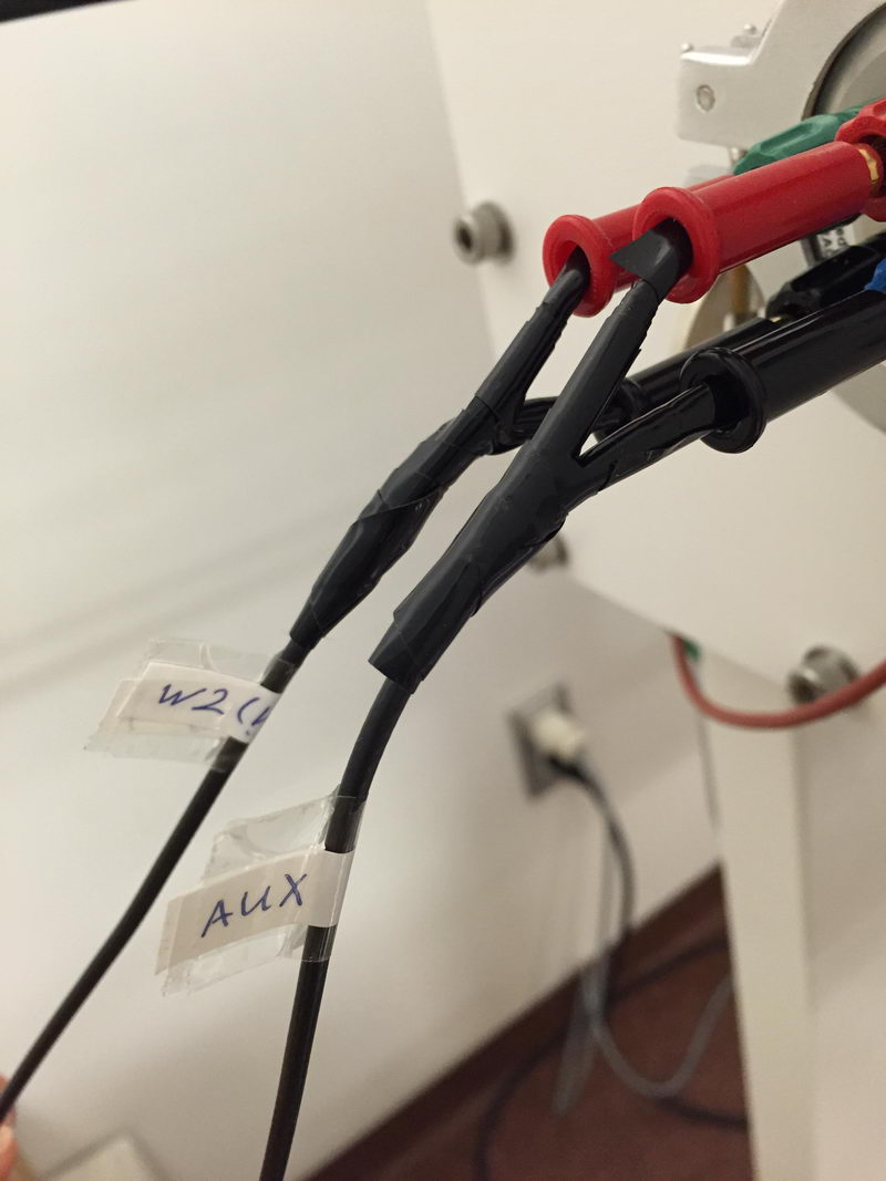
Cables for CV inside the glovebox are also all labeled, but be careful: color coding doesn’t work the same way outside the box and you have banana connectors from both sides, so be careful which one is connected to which cable inside (working electrode for CV is W1 "WORK"; W2 is for high current, like the yellow one in Faraday cage setup for CV outsitde the box).
But what exactly happens if you mix up the red one and the green one? Just for demonstration, I did it on purpose for ferrocene solution in TBAP/MeCN. But please don’t repeat this. This is not the right way.
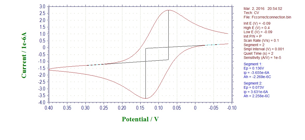
CV of ferrocene with electrode connected in the correct way:
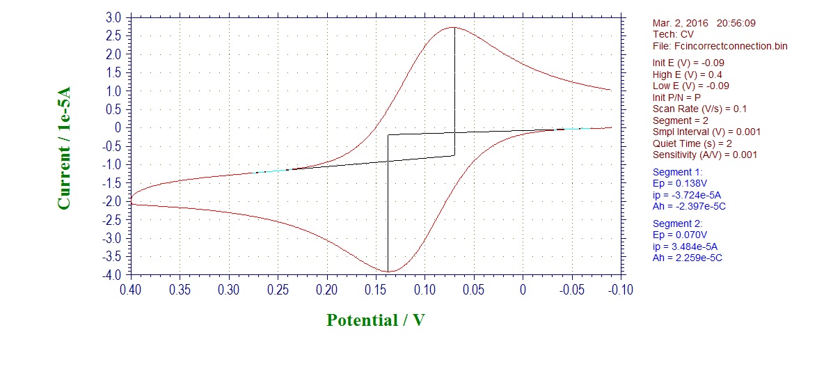
Incorrect connection CV (auxiliary connect to working, working to auxiliary):
Overlay (red - incorrect; blue - correct):
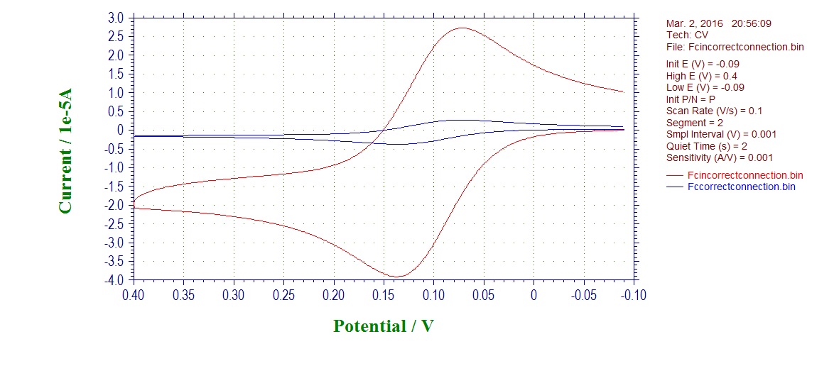
What you see first is that your current is much higher in case of incorrectly connected electrodes, as the area of Pt wire electrode is much larger than our CV disk electrodes. This should already raise suspicions if you see it.
What happened is that you start using Pt wire auxiliary as a working electrode now, and you use working disk electrode as an auxiliary. This is not good, because the reactions that now happen are not what you wanted, the potential is inverted. The electrodes may also be made of different materials and have difference surface area, and the working electrode may become contaminated by side-products forming due to high current going through small surface area electrode.
Things get worse in separated electrolysis cell, when you end up also having inverted potentials on the electrodes and different solutions in two chambers, large separation between working and reference, so incorrect potential.
Although the CV with incorrect connection looks almost reasonable, actually, this data cannot be properly analyzed, since Pt wire auxiliary that is used as working by mistake does not have a well-defined shape and area and we do not operate under any well-described diffusion regimes (it's neither planar nor spherical).
Since I did this CV where I mixed up on purpose the red wire with the green one, you can guess that this is probably not the worst crime. That is true, because the worst crime is when you connect either the red one or the green one to the reference electrode! This would be really disastrous! When by mistake, you connect your auxiliary or working cable to reference, you will start having an electrochemical reduction or oxidation happening DIRECTLY ON THE REFENCE ELECTRODE, which should stay intact and operate without any current going through it during CV measurements. This will eventually contaminate the membrane, change solution content inside the reference electrode, and change electrode surface. Eventually, this will destroy our precious and rather expensive reference electrode! This would be a really tragic event, so please don’t make this mistake.